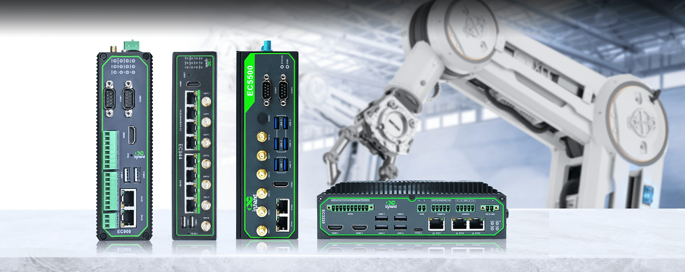
Endüstriyel Bilgisayarlar
-
Yüksek Performanslı AI İşleme Kapasitesi
TOPS’tan 100 TOPS’a kadar ölçeklenebilen yapay zeka işlem gücü sunar. Bu sayede görsel tanıma, nesne takibi ve karmaşık video analizleri doğrudan saha (Edge) üzerinde, buluta ihtiyaç duymadan gerçek zamanlı gerçekleştirilir. -
Gelişmiş Küresel Bağlantı Seçenekleri
5G, 4G LTE, Gigabit Ethernet ve Wi-Fi desteği ile dünyanın her yerinde kesintisiz iletişim sağlar. Zorlu sahalarda bile verinin ana merkeze aktarımı için güvenilir ve hızlı bir ağ altyapısı sunar. -
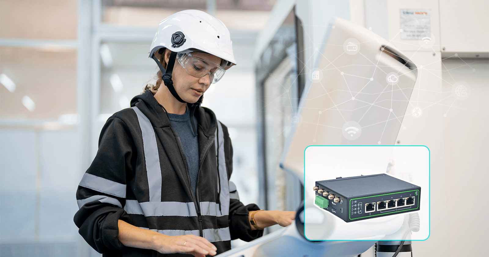
Endüstriyel Sınıf Dayanıklılık
Endüstriyel Sınıf Dayanıklılık: -20°C ile +70°C arası geniş çalışma sıcaklığı aralığına sahiptir. Fansız tasarımı, metal gövdesi ve yüksek EMC (elektromanyetik uyumluluk) koruması ile tozlu, titreşimli ve elektriksel gürültünün yoğun olduğu en ağır sanayi koşullarında sorunsuz çalışır. -
Hızlı Bulut Entegrasyonu ve Kolay Yönetim
DeviceSupervisor Agent yazılımı sayesinde programlama gerektirmeden AWS ve Azure gibi bulut platformlarına veri aktarabilir. Ayrıca Python ve Docker desteği ile geliştiricilere kendi özel uygulamalarını koşturabilecekleri esnek bir ortam sağlar.
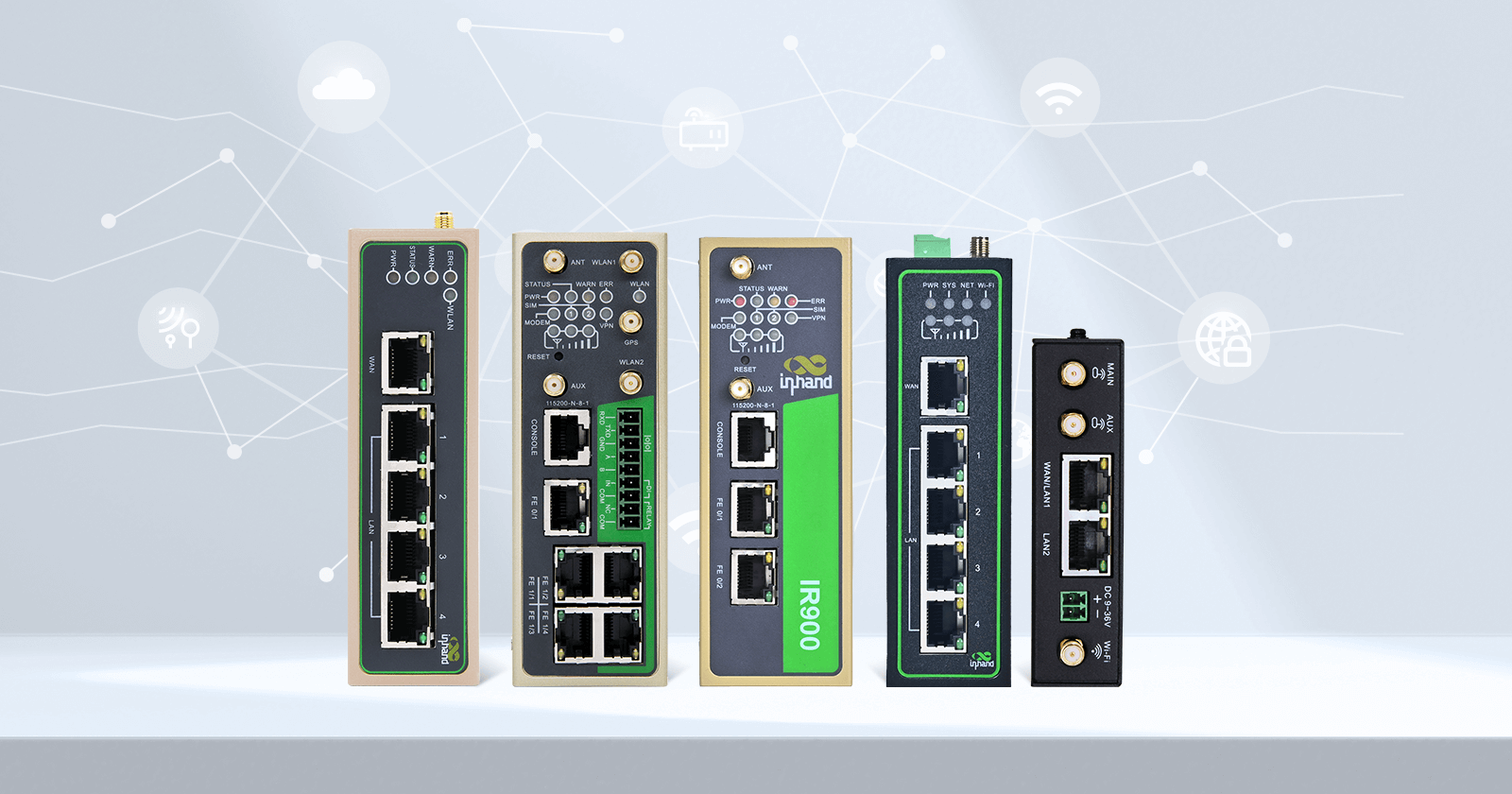
| Ürün | DETAY | ||
|---|---|---|---|
|
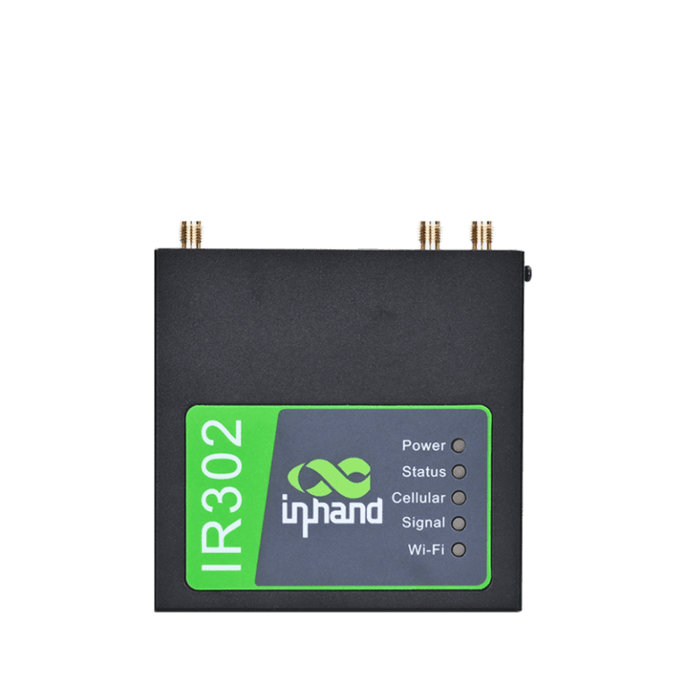
IR302 |
Hücresel: 4G |
Satın Al! |
|
IR315 |
Hücresel: 4G |
Satın Al! |
|
IR615 – S |
Hücresel: 4G |
Satın Al! |
|
IR624 |
Hücresel: 5G |
Satın Al! |
|
IR915 |
Hücresel: 4G |
Satın Al! |
Her zaman, her yerde birden fazla İnternet erişimi olanağı
- 5G hücresel ağ erişimi, SA/NSA
- CAT1/CAT4/CAT6, 2G/3G Fall-back desteği
- LTE CAT M
- NB-IoT
- Kablolu/ADSL erişimi
- Wi-Fi erişimi
Hayatınızı sınırsız bağlantı ile donatın!

Son Derece Güvenilir ve Kesintisiz İletişim
- İletişim için çoklu bağlantılar ve çoklu yedekleme mekanizmaları, kablolu, LTE hücresel ve Wi-Fi ağları arasında karşılıklı yük devretme
- Çift SIM yedekliliği
- VRRP
- Çok katmanlı bağlantı algılama mekanizmaları, otomatik tekrar arama ve hatalardan otomatik kurtarma

Kapsamlı Güvenlik Stratejileri
- Veri iletimi: IPsec VPN, L2TP, PPTP, GRE, WireGuard VPN, ZeroTier VPN, OpenVPN, DMVPN vb. dahil olmak üzere birden fazla VPN.
- Ağ koruması: SPI tüm durum tespiti, erişim kontrolü, anti-DDOS saldırıları, sanal IP eşleme, MAC-IP bağlama dahil olmak üzere eksiksiz güvenlik duvarı işlevleri
- Cihaz yetki yönetimi
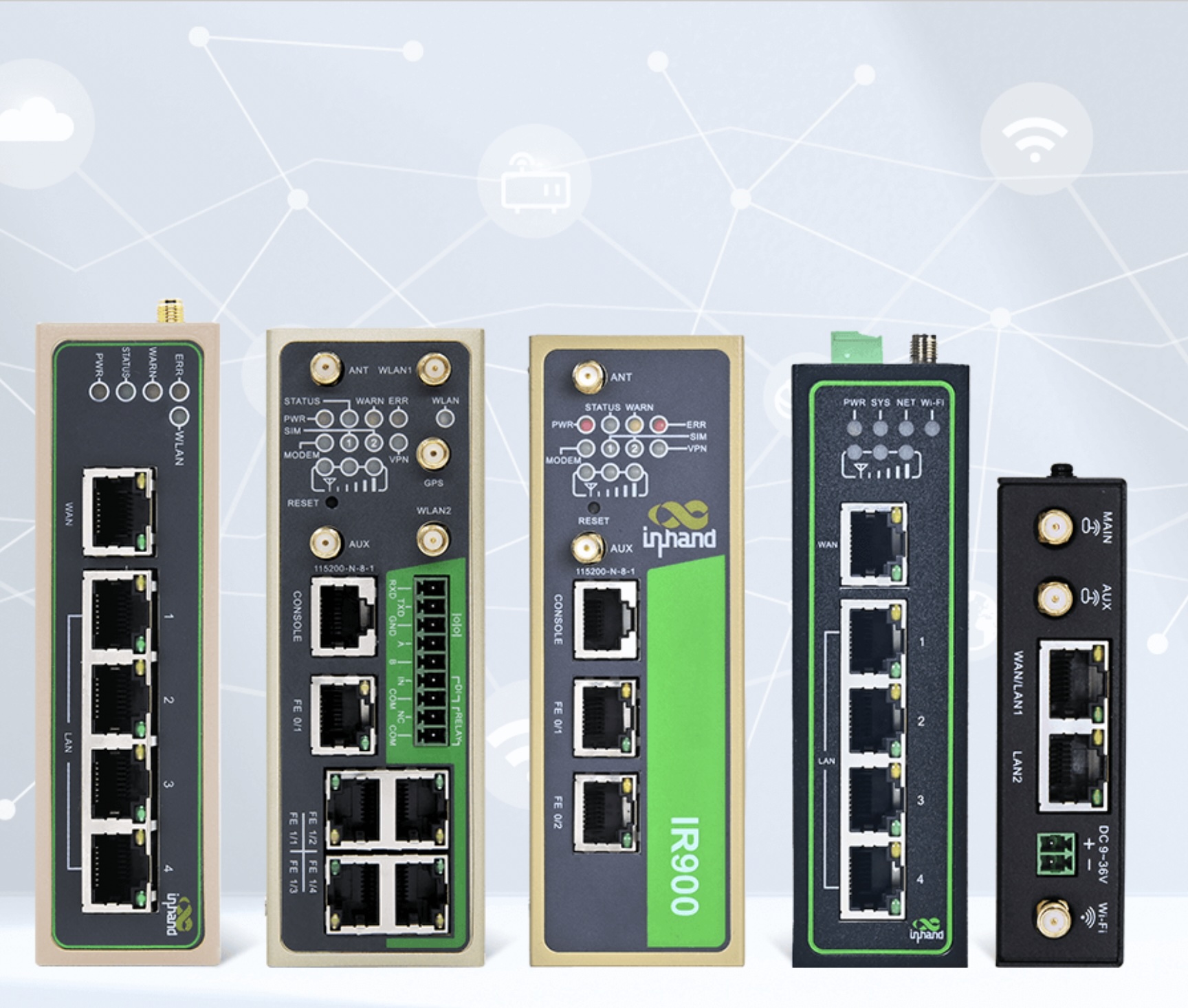
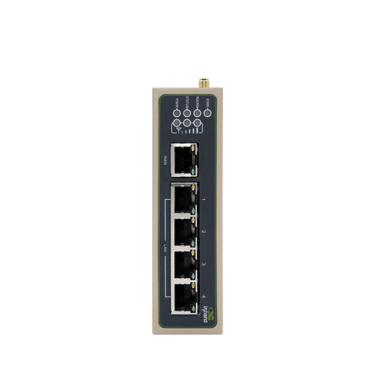
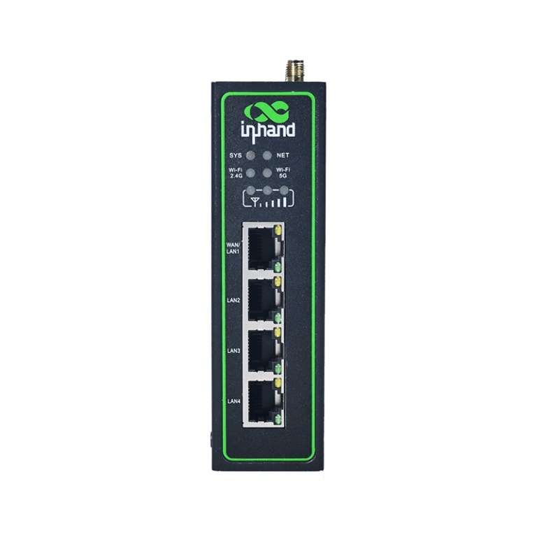
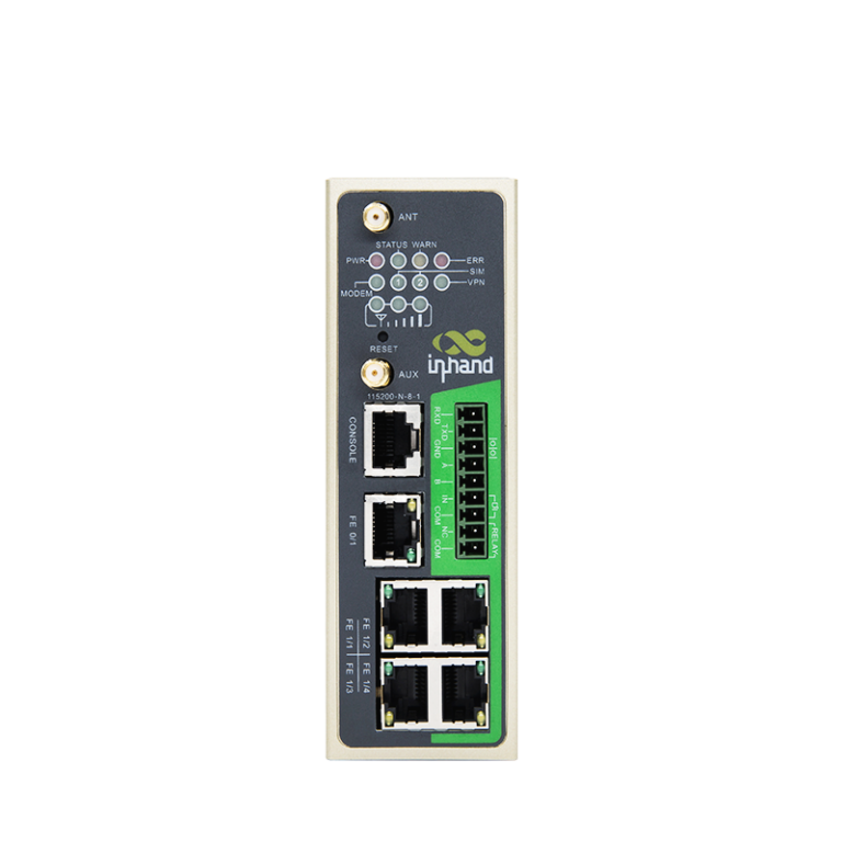
Zengin endüstriyel arayüzler
InHand endüstriyel yönlendiriciler, zengin donanım arayüzleri aracılığıyla esnek ve güvenilir ekipman ara bağlantısını gerçekleştirir.
- İnternet bağlantısı: Hücresel, Ethernet ve Wi-Fi
- Seri bağlantı noktaları: RS232, RS485
- DIO
- GNSS

Sağlam ve güvenilir, endüstriyel uygulamalar için özel olarak üretilmiştir
- Geniş sıcaklık ve voltaj aralıklarıyla tamamen endüstriyel sınıf tasarım
- Yüksek EMC seviyeleri
- Fansız soğutma
- IP30
- “DIN Rail (Ray) Montaj
İletişim
Merdivenköy Mah. Business İstanbul
Nur Sok. A Blok No:1/1 İç Kapı No: 41
Kadıköy 34732 İstanbul.
+90 216 340 7172
bilgi@avd.com.tr
